I wired motor drivers upto the Artemis, and finally integrated all of the components onto the car.
Prelab
Motor Driver Wiring
I used a separate motor driver for each motor so that I could wire the pins in parallel to supply the motors with double the current. However,
this could lead to timing issues where the motors are out of sync. I will deal with this later in the lab.
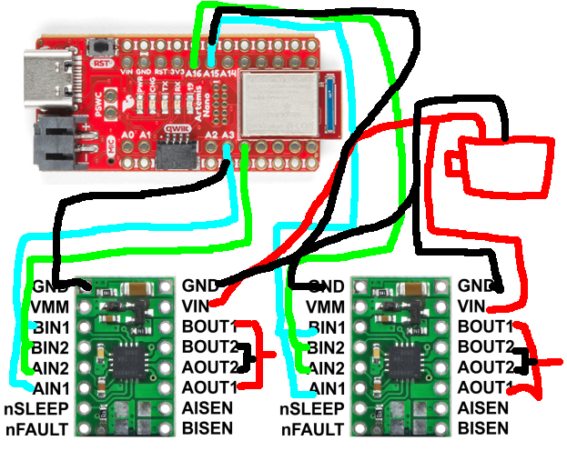 As shown in the wiring diagram,
- The ground pins on the left and right are wired to the Artemis and the negative terminal of the motor battery respectively.
- VIN is wired to the positive terminal of the battery
- AIN1, BIN1 are coupled and wired to pins 3 and 15 (for the two motor driver).
- AIN2, BIN2 are coupled and wired to pins 4 and 16
- AOUT1, BOUT1 are wired parallely to the positive lead of the motor
- AOUT2, BOUT2 are wired parallely to the negative lead of the motor
I used these pins specifically because they were PWM capable and gave me the most flexibility while soldering.
Separate batteries
This setup uses different batteries to power the Artemis and the motor because the peak current draw from the motors is much higher than what is ideal for the Artemis. Also, the motors generate a lot of electrical noise which would translate to noisy signals from the Artemis.
Lab
Testing the PWM
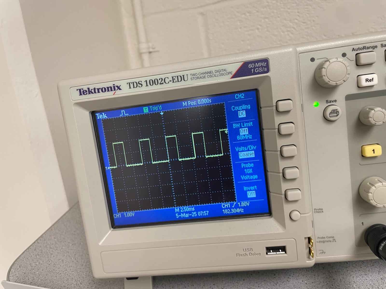
I wired the motor drivers upto the Artemis pins and then proceeded to test whether the PWM was working fine. I connected the oscilloscope probe
to AOUT1, and I sent 1,0 to IN1, IN2 respectively. Therefore, with a pwm value of 128, the expected result should be a square wave with roughly equal
length high and low sections. Also, I set the power supply to provide 3V, so the high peaks should occur at that value. I chose this because it is similar to
the battery voltage of 3.7V.
Motor Tests
Next, I wired the motor drivers upto the actual motors, and tested them. I sent a signal with width 128 along IN1 and 0 along IN2.
void setup() {
    pinMode(3, OUTPUT);
    pinMode(4, OUTPUT);
    pinMode(15, OUTPUT);
    pinMode(16, OUTPUT);
}
void loop() {
    analogWrite(3,128);
    analogWrite(4,0);
    analogWrite(15,128);
    analogWrite(16,0);
}
The motors running on battery input,
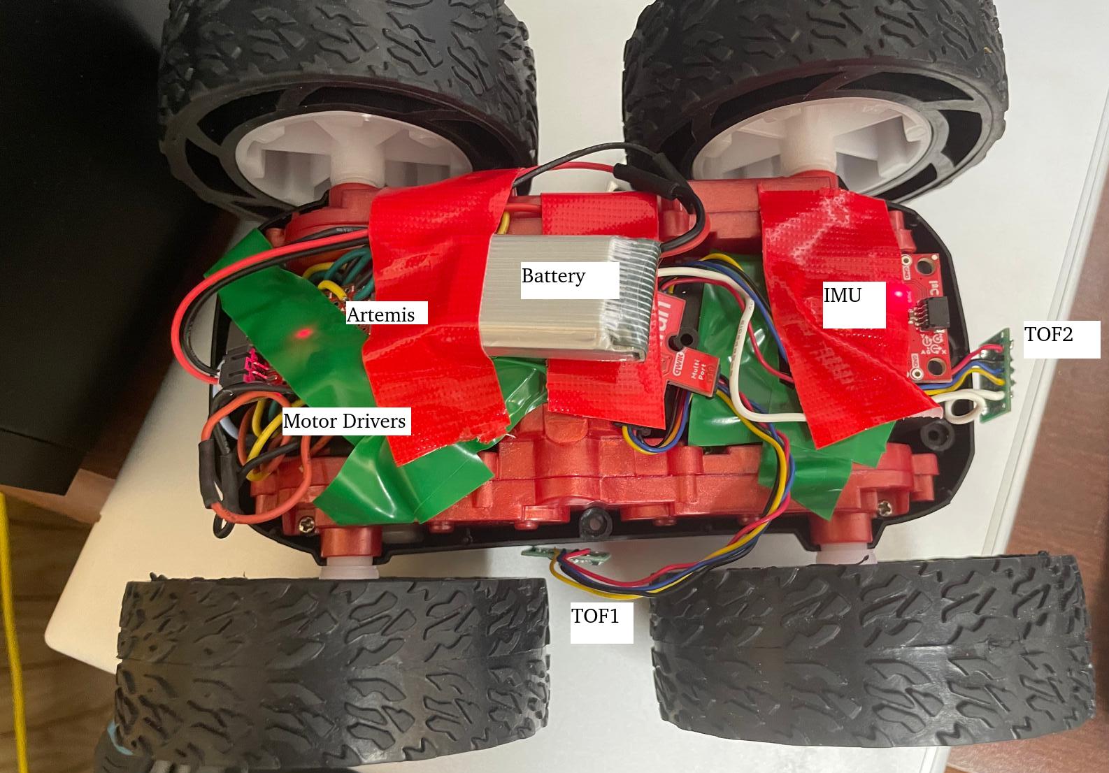
Assembled Car
Now, I put everything together using copious amounts of tape.
Lower Limit of PWM
To find the lowest limit at which the motors will overcome static friction, I started at 100 PWM and then went to 50, which I found to be the lowest setting at which the motors will move. When the robot was already moving, I found the lowest PWM setting to be 40. For turning, I found that a higher PWM of 75 is required.
Motor Calibration
As I talked about earlier, slight timing differences, and potentially other problems, caused the car to veer to the left when the
same input is provided to the motors. I found that travelling 1m the robot drifted 5cm.
 To combat this, I introduced a calibration factor of 0.95 to the right motor.
void loop(){
    int pwm = 128;
    analogWrite(3, 128);
    analogWrite(4, 0);
    analogWrite(15, 0);
    analogWrite(16,(int) (0.95 * 128));
}
Open loop control
I now made the robot drive forward and then spin twice. I saw that the turning was a little unreliable probably because my battery was discharged and I did not provide a very high pwm.
void set_motor_speed(int pid_val){
  int motor_out1 = pid_val;
  int motor_out2 = 0;

  if (pid_val < 0.0){
    motor_out2 = -pid_val;
    motor_out1 = 0;
  }
  analogWrite(3, motor_out1);
  analogWrite(4, motor_out2);
  analogWrite(15, motor_out2);
  analogWrite(16, motor_out1);
}

void turn(int pwm){
  int motor[4];
  if (pwm < 0.0){
    motor[1] = -pwm;
    motor[3] = -pwm;
  }
  else{
    motor[0] = pwm;
    motor[2] = pwm;
  }
  analogWrite(3, motor[0]);
  analogWrite(4, motor[1]);
  analogWrite(15, motor[2]);
  analogWrite(16, motor[3]);
}

void loop(void)
{
  while (millis() - startmillis < 1250){
    set_motor_speed(60);
  }
  startmillis = millis();
  while (millis() - startmillis < 1000){
    turn(90);
  }
  startmillis = millis();
  while (millis() - startmillis < 500){
    set_motor_speed(-60);
  }
  startmillis = millis();
  while (millis() - startmillis < 1000){
    turn(-90);
  }
  analogWrite(3, 1);
  analogWrite(4, 1);
  analogWrite(15, 1);
  analogWrite(16, 1);
}
Discussion
I had a few weird errors this lab where pressing the reset button on the Artemis would trigger the motors. I figured that this was because some connections were shorting so I spent some time soldering them again which resolved the problem.