During this lab, I implemented closed loop control via PID. The goal was to get the robot to stop exactly some distance from a wall.
Prelab
Bluetooth
Since tuning and debugging the PID controller requires a lot of iteration, I setup my bluetooth communication to receive the PID parameters from the remote computer, and then send back the data it collected.
case START_ROBOT:
{
    // get pid params
    char char_arr[8];
    success = robot_cmd.get_next_value(char_arr);
    if (success) kp = atof(char_arr);
    success = robot_cmd.get_next_value(char_arr);
    if (success) ki = atof(char_arr);
    success = robot_cmd.get_next_value(char_arr);
    if (success) kd = atof(char_arr);

    // Do pid
    pid();
    // Send back data after pid
    for (int i = 0; i < ARR_SIZE; i++){
        tx_estring_value.clear();

        tx_estring_value.append(times[i]);
        tx_estring_value.append(",");
        tx_estring_value.append(tof[i]);
        tx_estring_value.append(",");
        tx_estring_value.append(pwm[i]);
        tx_characteristic_string.writeValue(tx_estring_value.c_str());
    }
    break;
}
Then, on the python side my message handler looked like,
outs = []
def readdata(uuid, bytearray):
    outs.append(list(map(float, ble.bytearray_to_string(bytearray).split(",")))) # params are comma separated
P control
I started out with just P control which just drives the motor input proportionally to the position error. Also, I set the sensor mode to short because I was always testing < 1.4m of distance and this would allow for the quickest measurments. I additionally added a hard stop of 5s while testing, so I didn’t think I needed to account for bluetooth disconnect (which wouldn’t work with this kind of loop).
void pid(){

    while (start_time + 10000 > millis()){ // run for 10s at max
        // PID calculations
        if (!get_sensor_data()){
            int idx1 = (cnt - 1) % ARR_SIZE;
            int idx2 = (cnt - 2) % ARR_SIZE;
            sensor2_[cnt % ARR_SIZE] = sensor2_[idx1] + (sensor2_[idx1] - sensor2_[idx2]) / (times[idx1] - times[idx2])  * (times[cnt % ARR_SIZE] - times[idx1]); // estimate
        }
        float error = ((float) sensor2_[cnt % ARR_SIZE]) - targetDistance;
        set_motor_speed(kp * error);
    }
}

void set_motor_speed(float pid_val){
  int motor_out1 = min(pid_val, 200);
  int motor_out2 = 0;

  if (pid_val < 0.0){
    motor_out2 = min(-pid_val, 200);
    motor_out1 = 0;
  }
  analogWrite(3, motor_out1);
  analogWrite(4, motor_out2);
  analogWrite(15, motor_out2);
  analogWrite(16, motor_out1);
}

int get_sensor_data()
{
  times[cnt % ARR_SIZE] = millis();
  if ( !sensor2.checkForDataReady()) return 0;
  sensor2_[cnt % ARR_SIZE] = sensor2.getDistance();
  return 1;
}
Tuning
Tuning the controller was fairly straight forward, the only major issue I faced was that the PWM deadband which I resolved by just adding the minimum value of 45 to the motor outputs. Testing with Kp = 0.5,
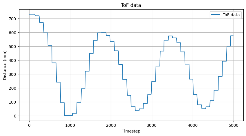
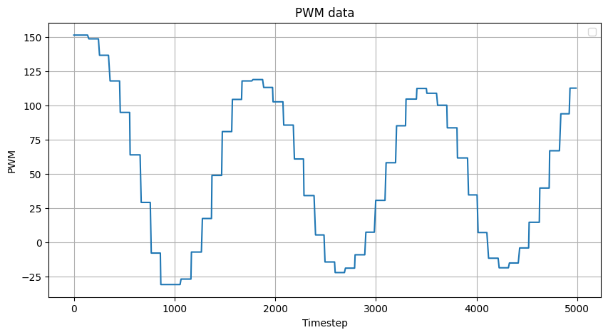
Clearly 0.5 is too high leading to very high oscillations.
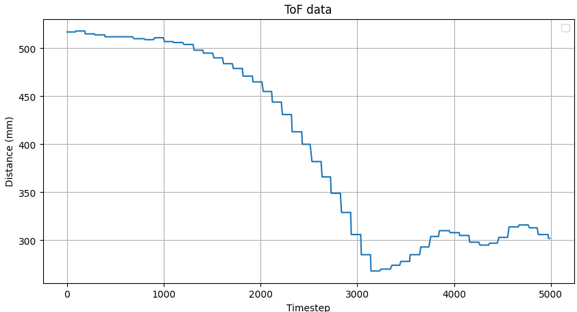
Next, I tried 0.05 which I found significantly reduced oscillations, but it also made the robot move significantly slower.
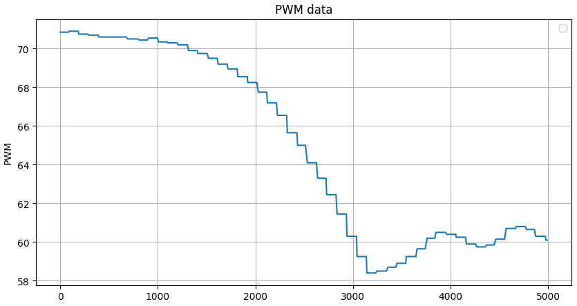
Speed discussion
Without extrapolation, my code would run at 50 Hz because the ToF sensor was a bottleneck. With the extrapolation (shown in the earlier code block), the loop runs at roughly 155 Hz so every 3 iterations I receive a new ToF reading. I think this causes a decent amount of the oscillation when the error is low because the simple linear extrapolation overshoots the target.
Discussion
I found that for this kind of linear control even P control produces a good controller. Also, in hindsight I think my minimum PWM setting was a little high which could have been another possible reason for getting the slight oscillations even with a Kp of 0.05.