Prelab
I2C address
The datasheet says that the I2C address should be 0x52
Using 2 ToF sensors
Since both the sensors have the same address, to communicate with each one distinctly I chose to first shut off one of the sensors via the XSHUT pin. Then, I change the address of the sensor that is on, and then I switch the first sensor back on.
Sensor placement
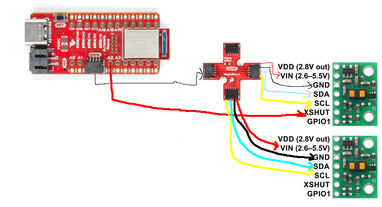 The diagram above demonstrates how I wired the ToF sensors to the Artemis via the breakout board. Effectively, I used Qwiic connectors and cutoff one
head and soldered the wires directly to the ToF sensors. Also, I connected one of the GPIO pins on the Artemis to the XSHUT of one ToF sensor (since only one ever needs
to be shut). I chose to use long wires to connect the ToF sensors because they will be placed on the sides of the car.
The diagram above demonstrates how I wired the ToF sensors to the Artemis via the breakout board. Effectively, I used Qwiic connectors and cutoff one
head and soldered the wires directly to the ToF sensors. Also, I connected one of the GPIO pins on the Artemis to the XSHUT of one ToF sensor (since only one ever needs
to be shut). I chose to use long wires to connect the ToF sensors because they will be placed on the sides of the car.
Lab Tasks
ToF Sensor
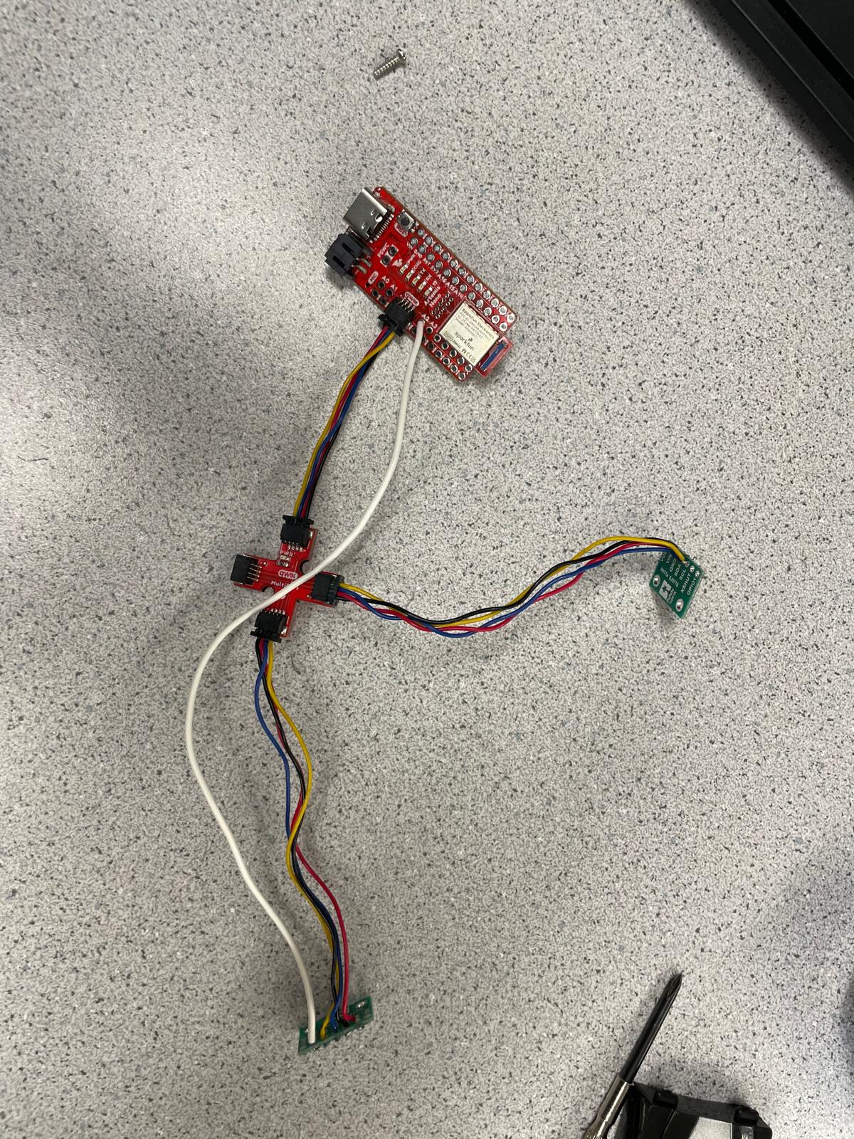
The picture above shows how I connected the ToF sensors via the breakout board to the Artemis. Also, I soldered a wire to connect the XSHUT on one ToF and GPIO pin 2 on the Artemis.
Scanning for I2C address
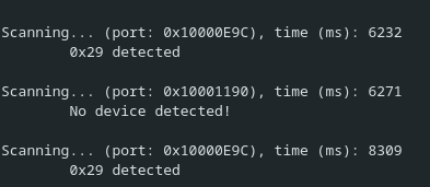
The picture above shows the Artemis detecting a device at I2C address of 0x29. This is not the expected 0x52; however, 0x52 is just 0x29 left shifted by one bit because the program ignores the read/write bit that is the LSB of an I2C address.
Data and Testing
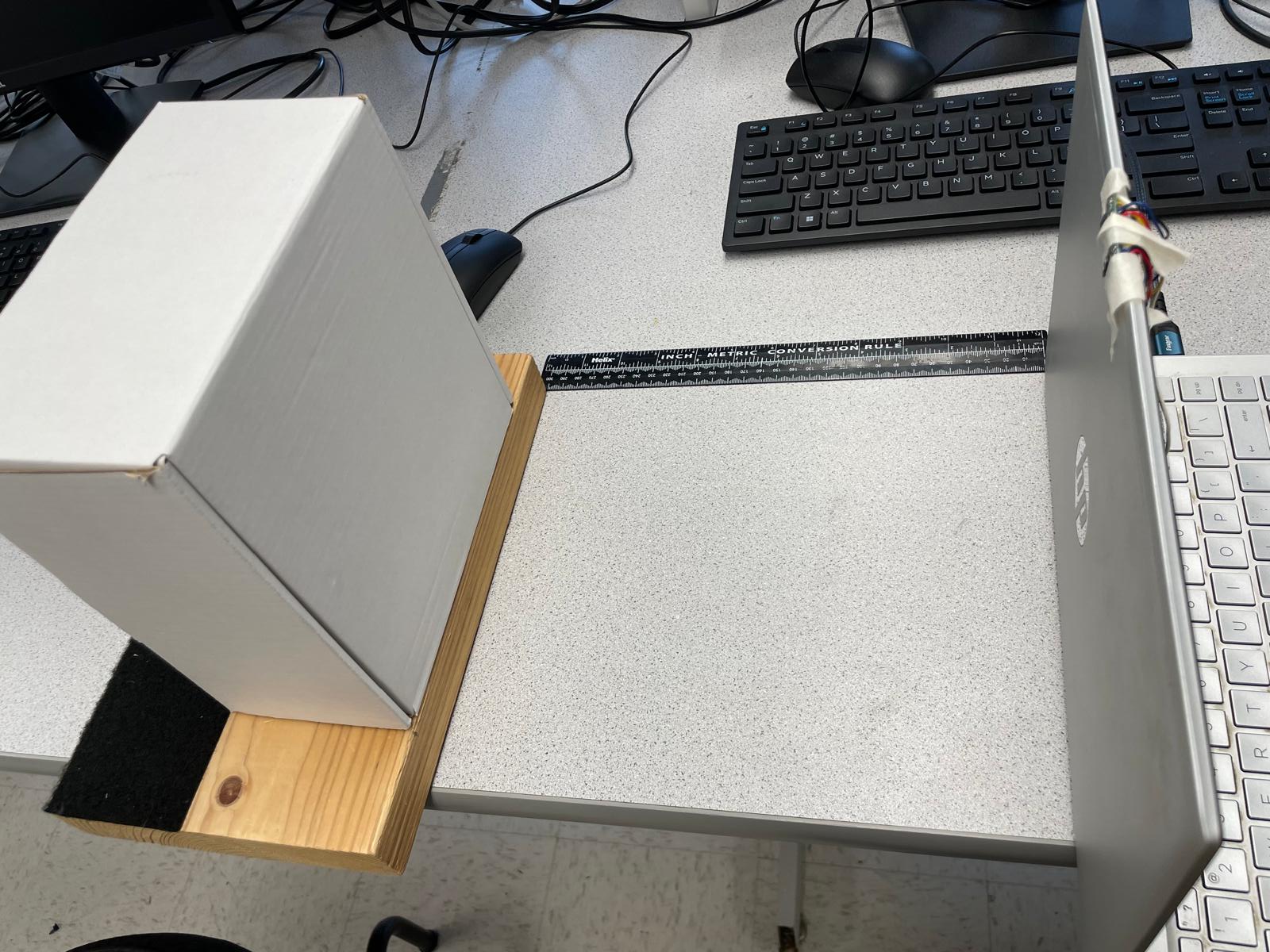
I decided to test the short distance mode because it was easier for me to verify that these readings were correct using a ruler. The short distance mode has a range of 0.05m - 1.3m. I then took 100 readings per distance.
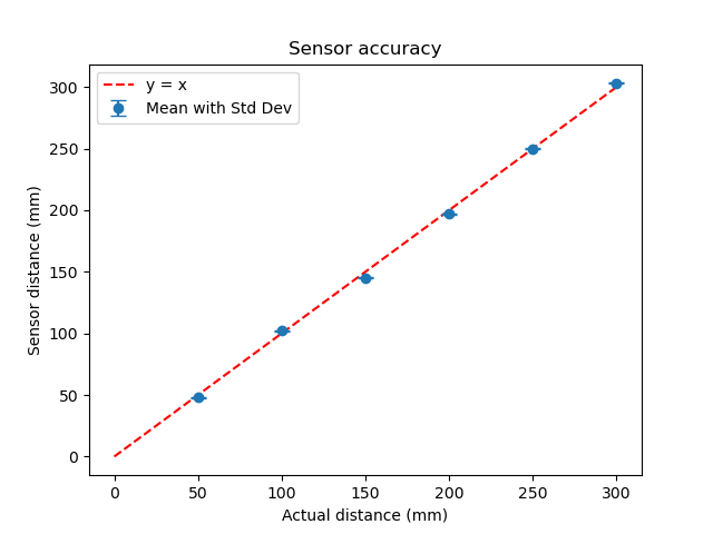
I graphed the data for measurements from 5cm to 30cm. The precision of the sensor was very high with negligeble standard deviation among the 100 measurements. Also, the largest error I saw was 3.3%.
ToF and IMU readings
Using code from lab 2 to read in IMU data, and I used the XSHUT along with changing one I2C address to read the ToF data from both sensors as shown in the snippet below.
sensor2.sensorOff();
Wire.begin();
sensor1.setI2CAddress(0x54);
sensor1.setI2CAddress(0x54);
sensor1.begin();
sensor2.sensorOn();
sensor2.begin();
sensor1.setDistanceModeShort();
sensor2.setDistanceModeShort();
sensor1.startRanging();
sensor2.startRanging();
ToF Sensor Speed
if (!sensor1.checkForDataReady() || !sensor2.checkForDataReady())
{
    waiting_++;
    return;
}
int distance = sensor1.getDistance(); //Get the result of the measurement from the sensor
int distance2 = sensor2.getDistance(); //Get the result of the measurement from the sensor
cnt++;
times[cnt] = millis();
if (cnt == 100){
    Serial.printf("Waited for %d cycles for 100 measurements\n", waiting_);
    int mean = 0;
    for (int i = 1; i< 100; i++){
        mean += times[i] - times[i-1];
    }
    Serial.printf("Mean time between measurements %d\n", mean/100);
}
I used the code above to figure out what the limiting factor was in taking ToF sensor readings. I saw that the sensor waited for 1984 cpu cycles to obtain 100 measurements (so 1984 out of 2084 cpu cycles was just waiting for the sensor). Therefore, clearly receiving sensor readings was the bottleneck. Also, the time between two sensor readings was 19 ms.
Time v Distance, Angle
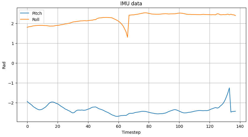
I adapted the code from lab 1 and 2 to send both the distance data from both the IMUs and the roll and pitch data from the IMU. I
added a new command GET_TOF_IMU_DATA which sent a string with the time, angle and distance data.

Discussion
This was my first time soldering and I learnt a lot about the best practices for different kinds of soldering. Also, normally I would just assume sensors are accurate enough, but actually going through the excercise was interesting and I think it will be helpful for debugging later on.